
CyPro bonus

March 28, 2025
This learning module is part of the building block:
After having established the context, the next step in risk management is to model the system under assessment. The outcome of this process is the system architecture and/or data flow diagram.
The second step in risk management is system modelling, which includes making a model of the system (or product) that is being assessed.
The purpose of system modelling is to identify the elements that form the system and their connections. This process lays the foundation for achieving a common understanding of the system under evaluation and enables to reason about data flows between components. The architecture can be described at various levels of detail, depending on the task at hand.
Prior to identifying the threats, we need to define the system we want to assess, including related components and their interconnections.
System modelling is usually conducted as a workshop, often supported by purpose-made tools. In case you do not intend to use any specific tools, you will need a whiteboard/flipboard along with coloured markers, stickers, pens, and printed versions of the worksheet. It is recommended to carry out the discussion using paper/whiteboard rather than a computer, so that all participants have the opportunity to be involved.
When assessing an existing system/product, it also pays off to review the existing design documentation and refer to it throughout the assessment.
Allocate at least an hour for system modelling. It is recommended to strive for diversity in this process, ensuring that both individuals with business understanding and technical insight participate.
An important part of the risk management is to have a clear picture of what we want to analyse, i.e., the full overview of the system architecture. This overview will facilitate the discussion about the assets and threats.
To make sure that all participants in the workshop are aligned as to what is being analysed, it is advisable to agree on some common definitions. The context establishment already provides an overall delimitation/definition of the system, but it may be a good idea to revisit and refine the description if needed. If there are architectural diagrams or other technical descriptions available, they can also be a good starting point. However, be aware that architectural diagrams typically contain a lot of information and can be challenging for non-technical individuals to understand. Hence, to ensure that all participants have an understanding of the system, it is advisable to create a relatively abstract drawing from scratch and focus only on the major components. For example, it is not uncommon for a client and a server to communicate with each other in different ways (REST, WebSocket, etc.), just as the server internally may consist of various microservices. Including all these details in the diagram could quickly become a bit overwhelming. After all, this information is not needed until the later steps (Asset analysis and Threat identification). Instead, the emphasis should be on the major components, and the communication between A and B can simply be marked on the diagram.
![]()
Draw your system
Printable version of the tool in large format
The process of drawing the system model follows the following steps:
Find further inspiration in the IoT door lock example below.
Let’s investigate our IoT door lock example that we use as a running example throughout the risk management process.
The example consists of an interconnected network of hardware, software, and communications systems, including the IoT door lock hardware with a communication module, a hub, a mobile application for remote access and a cloud infrastructure for data storage and processing.
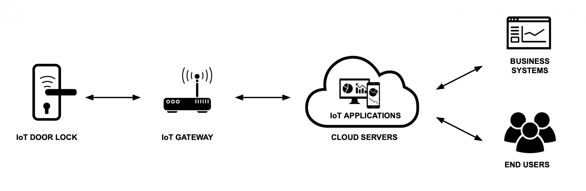
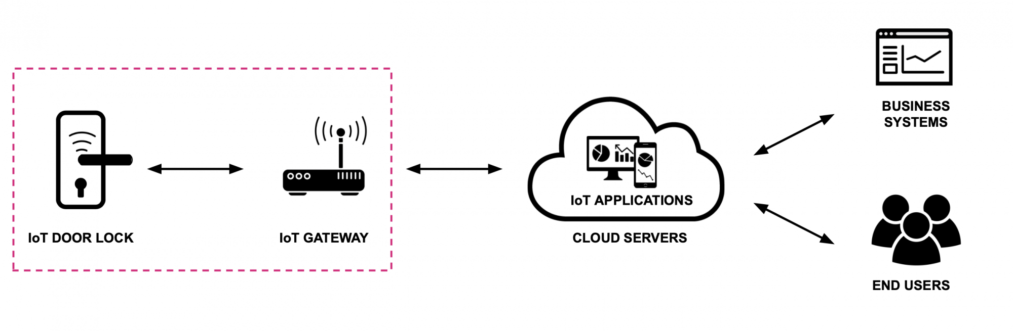
The output of the process is the system and data flow diagrams. The diagram gives you an overview of your system and how it interacts with external entities. The identified trust boundaries reveal the extent of control you have (or do not have) over these elements, thus highlighting potential attack surfaces.
It is beneficial to involve both individuals with business understanding and technical insight in the system modelling step as it helps build a shared understanding of the system.
After drawing the system diagram, the next step is to identify the assets that are important to the organisation. This is described in more detail in Asset identification.

The contents described above have been developed in the project:
’CyPro – Cybersecure manufacturing in Denmark’ by Aarhus University, Alexandra Institut, DAMRC, UGLA Insights and FORCE Technology funded by The Danish Industry Foundation. Material from the project is published under Creative Commons.
Get your certificate for this completed building block. Request the certificate and we will send you the personal certificate.


